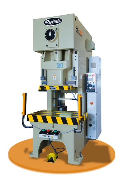
Cross-Shaft Precision Press
Cross-Shaft Precision Press
Standard Equipment
- Pneumatic Dry Clutch
- PLC Control With Fault Finding System
- Auto Grease Lubrication System
- Motorized Slide Adj.
- Knock Out System
- Die Height Indicator
- Counter Balancer of Slide
- Anti-repeat Safety Device
- Air Outlet / Miss-Feed Detector Socket
- Rotary Cam Limit Switch
- Electric Control Panel and Production Counter
- Operation & Maintenance Manual
- SMC/FESTO Make FRL & Pneumatic Fitting
- ROSS/ Toyoki Japan Make Dual Solenoid Valve
Optional Equipment
- Power Take Off Shaft
- Pneumatic Die Cushion
- Variable Speed Drive
- Photo Safety Curtains
- Variable Stroke Adj.
- Quick Die Changer
- Extra Base Plate
- Inclinable Type
- Anti-Vibration Mount
FRAME CONSTRUCTION
Cross Shaft Precision Press fabricated from IS-2062 graded rolled steel plates. Frame is deeply reinforced and fines machines after stress reliving. The interlocked design put the direct support to frame. This frame is strain free and eliminates welds at load supports. Thus the accuracy of the machine is never disturbed. High Precision Transmission Gear: The high accurately machined gear system provides smooth and silent operation.
TABLE & SLIDE (RAM)
Table and Slide are made of high grade heavy duty cast iron and properly seasoned. They are perfectly aligned, to each other to obtain high accuracy and precession press operation.
LONG HEXAGONAL GIBS
Durable alloy bronze lining fixed directly on the frame without the defect of losing adjusting bolts. Durable lining can also maintain high accuracy and extend the life of tooling.
FLYWHEEL
Properly sized flywheel is made of high grade cast iron, for storing and releasing adequate energy for the cutting operations, and properly balanced for smooth running.
HIGH QUALITY CRANK SHAFT
The strong crank shaft with outstanding rigidity ensures that accuracy can be maintained under qualified standard and extends the life of tooling.
MOTORIZED SLIDE ADJUSTING DEVICE
The Motorized slide adjusting device is adopted with a thin brake motor and operated with push buttons. It provides stable positioning accuracy and quick adjustment.
AUTO LUBRICATION SYSTEM
The auto lubrication system with default monitor ensures high reliable operation.
DUAL SAFETY VALVE
The interlock mechanism on the dual valve keeps the clutch and brake from mis-actuation when valve is default.
DIE HEIGHT INDICATOR
Motorized slide adjusting devise fitted with 0.1 mm increment digital die height indicator.
HYDRAULIC OVERLOAD PROTECTOR
The Hydraulic overload protector is installed to prevent the overloading from exceeding the rating capacity tonnage and protect press and tooling from damage. The simple resetting process makes the restart operation easily.
PNEUMATIC DRY CLUTCH
The fail-safe, pneumatically operated clutch brake combination is designed to provide excellent slide motion control even at high speeds. Adequate energy required for blanking operation is ensured by optimised design of the flywheel.
Well Maintained
Modern Equipments
All Expert Engineers
Power Efficient Factory
Technical Parameters
| Model No. |
RX - 25 | RX - 35 | RX - 45 | RX - 63 | RX - 80 | RX - 110 | RX - 160 | RX - 200 | RX - 250 | |||||||||
| NG | SG | NG | SG | NG | SG | NG | SG | HG | SG | HG | SG | HG | SG | HG | SG | HG | SG | |
| Tonnage | 25 | 35 | 45 | 63 | 80 | 110 | 160 | 200 | 250 | |||||||||
| Fix Stroke (D) | 35 | 80 | 40 | 90 | 50 | 110 | 50 | 130 | 60 | 150 | 70 | 160 | 80 | 200 | 90 | 220 | 100 | 250 |
| Adjustable Stroke | 8-80 | 8-88 | 8-80 | 8-88 | 8-50 | 8-88 | 8-50 | 8-100 | 8-60 | 8-100 | 8-70 | 8-125 | - | 8-160 | - | - | - | - |
| SPM (Fix) | 140 | 90 | 150 | 80 | 140 | 70 | 130 | 60 | 100 | 60 | 80 | 50 | 80 | 40 | 65 | 35 | 55 | 30 |
| SPM (Variable) | 80-180 | 70-110 | 100-200 | 60-90 | 100-180 | 50-80 | 100-160 | 40-70 | 60-130 | 40-70 | 60-120 | 35-60 | 50-100 | 30-50 | 40-80 | 25-45 | 30-70 | 25-40 |
| Rating Point (B.D.C.) | 2.3 | 3.2 | 1.2 | 3.2 | 1.5 | 3.2 | 1.5 | 4 | 3 | 4.5 | 3 | 5 | 3.5 | 6 | 3.5 | 6 | 4 | 6 |
| Die Height (D.H.) | 230 | 250 | 270 | 300 | 330 | 360 | 400 | 450 | 450 | |||||||||
| Slide Adjustment (G) | 50 | 50 | 60 | 70 | 80 | 90 | 100 | 110 | 120 | |||||||||
| Slide Area (P x Q) | 330 x 250 | 380 x 300 | 430 x 350 | 500 x 400 | 560 x 460 | 650 x 520 | 720 x 580 | 860 x 650 | 960 x 720 | |||||||||
| Shank Hole | 38.1 | 50.8 | 50.8 | 50.8 | 50.8 | 63 | 65 | 80 | 80 | |||||||||
| Bolster Area (E x F) | 700 x 300 | 780 x 400 | 840 x 440 | 900 x 520 | 1050 x 600 | 1150 x 680 | 1250 x 780 | 1400 x 840 | 1500 x 900 | |||||||||
| Bolster Thickness (T) | 85 | 85 | 110 | 120 | 140 | 140 | 160 | 180 | 180 | |||||||||
| Floor to Top of Bolster (Z) | 800 | 800 | 800 | 860 | 900 | 900 | 900 | 1000 | 1000 | |||||||||
| Clear Distance Between Upright (R) | 394 | 490 | 495 | 580 | 620 | 670 | 760 | 900 | 940 | |||||||||
| Main Motor | 3 x 4 | 3 x 4 | 5 x 4 | 7.5 x 4 | 7.5 x 4 | 10 x 4 | 15 x 4 | 20 x 4 | 25 x 4 | |||||||||
| Variable Motor | 5 x 4 | 5 x 4 | 7.5 x 4 | 10 x 4 | 15 x 4 | 15 x 4 | 20 x 4 | 25 x 4 | 30 x 4 | |||||||||
| Slide Adjustment Motor | - | - | - | 0.4 | 0.4 | 0.4 | 0.75 | 1.5 | 1.5 | |||||||||
| Front Size Fix (A + B) | 830 x 1130 | 830 x 1130 | 855 x 1295 | 990 x 1420 | 1030 x 1475 | 1160 x 1680 | 1300 x 1985 | 1480 x 2140 | 1610 x 2450 | |||||||||
| Front Size Adjustment (A x B) | 750 x 1058 | 830 x 1130 | 855 x 1295 | 990 x 1420 | 1030 x 1475 | 1160 x 1680 | 1300 x 1985 | 1480 x 2140 | 1610 x 2450 | |||||||||
| Position of Anchor Bolts Fix (M x N) | 620 x 860 | 740 x 1000 | 765 x 1175 | 890 x 1180 | 930 x 1355 | 1060 x 1380 | 1180 x 1655 | 1360 x 1755 | 1470 x 2060 | |||||||||
| Position of Anchor Bolts Adjustment (M X N) | 620 x 860 | 740 x 1030 | 765 x 1175 | 890 x 1180 | 930 x 1355 | 1060 x 1380 | 1180 x 1655 | 1360 x 1755 | 1470 x 2060 | |||||||||
| Floor Space Required Fixed (W X L) | 893 x 1280 | 1230 x 1430 | 1255 x 1595 | 1390 x 1720 | 1430 x 1775 | 1560 x 1980 | 1700 x 2285 | 1880 x 2440 | 2010 x 2760 | |||||||||
| Floor Space Required Adjustment (W X L) | 893 x 1280 | 1230 x 1430 | 1255 x 1615 | 1390 x 1720 | 1430 x 1775 | 1560 x 1980 | 1700 x 2285 | 1880 x 2440 | 2010 x 2760 | |||||||||
| Die Cushion | ||||||||||||||||||
| Tonnage | 2.2 | 3.5 | 3.5 | 6 | 6 | 8 | 10 | 14 | 14 | |||||||||
| Stroker Length | 50 | 50 | 50 | 70 | 70 | 90 | 100 | 110 | 120 | |||||||||
| Pressure Pad Area | 300 x 210 | 300 x 210 | 300 x 210 | 380 x 260 | 410 x 260 | 480 x 300 | 540 x 340 | 640 x 440 | 740 x 540 | |||||||||
*All dimensions are in mm
- Have any Query?